Analytic Journal is growing – your feedback shapes the platform.Send feedback
Spectroscopy | Gas Analysis | Functional SafetyArticle
NDIR Gas Analysis from URAS to Today: Why the Physics Favours SIL and Replacement Becomes the Problem
- Author:
- Dusko Kadijevic, Publisher Analytic Journal
- Last updated:
- 21 October 2026
- Reading time:
- approx. 9 minutes
- Target audience:
- Process engineers, instrumentation and maintenance managers, plant safety managers, plant planners
Definition
NDIR gas analysis (non-dispersive infrared absorption measurement) determines the concentration of infrared-active gases such as CO, CO₂, CH₄ or SO₂ from the absorption of infrared radiation in a measuring cell. Selectivity does not come from splitting the spectrum, but from gas-filled detectors and optical filters.
Why does this topic matter?
The measuring principle is old, and so are many of the devices. In many plants NDIR analyzers have been running for 30 years or more, some of them as part of a protective function. The real question is therefore rarely whether the principle works. It is: how long can the device still be sourced, maintained and replaced?
This article has three parts. It explains why a measuring principle whose selectivity sits in the hardware is particularly suited to safety-related applications. It traces how the principle has developed since the URAS of 1938. And it shows why old devices cannot simply be swapped for new ones.
Three things come together here: the maintenance knowledge retires with the experienced colleagues, spare parts get scarce, and in my observation new devices last less long. Replacement therefore has to be planned early, not at the point of failure.
Operating principle
An NDIR analyzer sends infrared radiation through a measuring cell through which the sample gas flows. Gases that absorb in this wavelength range attenuate the radiation. According to the Lambert-Beer law, the attenuation is related to the concentration.
The special feature of the classical design: the detector itself is filled with the target gas and therefore responds only to that gas's absorption wavelengths. The light is not split by a prism or grating. If the absorption bands of an interfering gas overlap with those of the target gas, a filter cell containing the interfering gas is used, one cell per interferent.
| Component | Function |
|---|---|
| IR radiation source | provides broadband infrared radiation |
| Chopper (rotating shutter) | modulates the radiation so the detector delivers an alternating signal and drift is suppressed |
| Sample cell | sample gas flows through it |
| Reference cell | filled with a non-absorbing gas (typically nitrogen), provides the reference |
| Filter cell | removes overlapping absorption bands of an interfering gas |
| Optopneumatic detector (Luft detector) | two gas-filled chambers in which absorbed radiation creates pressure differences, evaluated capacitively or by a flow sensor |
| Evaluation electronics | converts the detector signal into the measured value and the output signal |
Typical absorption wavelengths are about 4.26 µm (4,260 nm) for CO₂ and 4.67 µm (4,670 nm) for CO. The actual filter and detector bands are device- and manufacturer-specific. Water vapour absorbs across wide parts of the infrared range and is therefore the most frequent cross-sensitivity. It must be considered when designing the measurement.
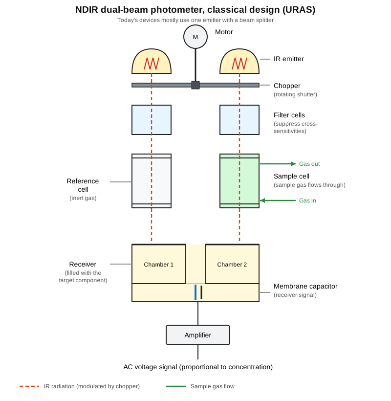 Principle schematic of an NDIR dual-beam photometer in the classical design (URAS): two emitters, chopper, filter, reference and sample cell, receiver with membrane capacitor. Today's devices are built differently, see the two following sections. Source: Analytic Journal.
Single-beam photometer with a two-layer receiver (UNOR)
A third design sits between the URAS and today's analyzers. Karl Friedrich Luft developed it from 1957 at the Steinkohlenbergbauverein in Essen, specifically for rapid CO measurement underground to counter mine fires. The instrument reached the market as the UNOR.
The new element was the two-layer receiver. A radiation-transmitting window divides the receiver into two chambers placed one behind the other, both filled with the target component and irradiated in sequence. The front, shorter chamber mainly absorbs radiation from the centres of the absorption lines, the rear, longer one the radiation from their flanks. A membrane capacitor measures the difference between the two optopneumatic signals.
The gain lies in selectivity. Choosing the chamber lengths allows cross-sensitivity from accompanying gases to be minimised, and it does so without a second cell. The design manages with a single beam path.
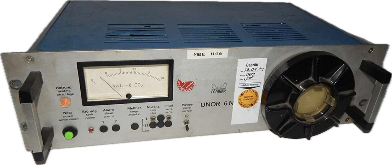 Maihak UNOR 6N as a 19-inch rack unit. Analogue pointer display with a vol.-% CO₂ scale, labelling in three languages, controls for heating, fault, alarm 1 and alarm 2, measuring range, zero, sensitivity and pump. The unit shown is a CO₂ version; the test label carries a date from 2017. Source: cadeex, reproduced with kind permission.
Two things about this design are worth noting. The two limit contacts, alarm 1 and alarm 2, sit directly on the instrument, so limit monitoring needs no additional logic. And the display is an analogue pointer instrument, on which a creeping loss of signal is noticed only if somebody watches the pointer over time or checks regularly with test gas.
In February 1962 the instrument won first prize in a competition held by the European Coal and Steel Community in Luxembourg to improve mine safety. The manufacturing licence went to Maihak AG of Hamburg, which followed in 1963/64 with the UNOR 2 for CO, CO₂ and CH₄. Later instruments of the series such as the UNOR 6N are documented in university theses as detectors in off-gas analysis and were likewise used for CO.
How today's devices are built
Today's gas analyzers are more compact. The device manual of a current NDIR analyzer describes a design that manages with a single IR source. A beam splitter creates the measuring and reference beam from it and at the same time acts as a gas-filled filter cell. The chopper interrupts both beams alternately, so that a single detector sees them one after the other.
The detector there is a two-layer detector. Its two chambers are connected by a microflow sensor rather than by a membrane capacitor. Optically this remains a dual-beam photometer, even though only one source is fitted.
The receiver principle itself is not new. After the UNOR patent expired, both Siemens and Hartmann & Braun took it up, Siemens in the Ultramat 5 with a transirradiated four-chamber receiver, Hartmann & Braun in the URAS 3 with a partially layered four-chamber receiver. In both cases the aim was the same as in the UNOR: lower cross-sensitivity.
Alongside this, a design has become established that needs neither a reference cell nor a gas-filled detector: the single-beam filter photometer.
Single-beam filter photometer
Here there is only one optical path and one cell. The reference is not created spatially via a second cell, but in time. A rotating filter wheel brings different filters into the beam one after another, among them a wavelength at which the target component does not absorb. The concentration follows from the ratio of the measuring signal to the reference signal.
Manufacturer documents name two methods for this. In interference filter correlation, narrowband filters select the wavelengths. In gas filter correlation, a gas-filled cell sits in the wheel and reproduces the spectrum of the target component. Because each filter serves its own wavelength, one device measures several components one after another in the same optical path.
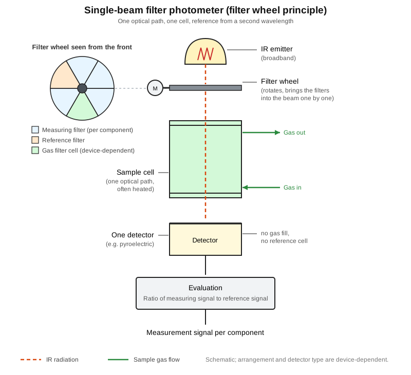 Single-beam filter photometer: one optical path, one cell, rotating filter wheel with measuring and reference filters, one detector without a gas fill. The concentration follows from the ratio of measuring signal to reference signal. Source: Analytic Journal, schematic, after manufacturer documents.
The detector here is not filled with the target gas; the filters provide the selectivity. Manufacturer data reach up to six components determined simultaneously and filter wheels with up to eight wavelengths. Some of these devices cover more than the classical infrared window and extend into the near infrared or the visible range. Arrangement and detector type differ from device to device and are rarely stated in full in the data sheet.
| Design | Optical path | Selectivity from | Detector | Typical use |
|---|---|---|---|---|
| Classical (URAS) | two emitters, sample and reference cell | detector gas fill, filter cells | optopneumatic, with membrane capacitor | single-component measurement, many legacy devices in service |
| Single-beam with two-layer receiver (UNOR) | one optical path, no reference cell | two-layer receiver, chamber lengths against cross-sensitivity | optopneumatic, two chambers in series, membrane capacitor | originally CO underground, later off-gas and process analysis |
| One IR source with beam splitter | one source, two optical paths | detector gas fill, beam splitter as filter cell | two-layer detector with microflow sensor | today's gas analyzers, one to a few components |
| Single-beam filter photometer | one optical path, one cell | interference filters, gas filter cell, reference wavelength | device-dependent, no gas fill, for example pyroelectric | multi-component measurement, up to six components |
The classification is editorial and describes widespread designs, not a complete market overview.
What matters is what all four designs have in common: selectivity sits in the hardware, in the detector's gas fill or in the filters. No spectrum is evaluated through a calibration model. This is exactly what the safety argument in the next section builds on.
From URAS to today
The URAS (Ultra-Rot-Absorptions-Schreiber, "ultra-red absorption recorder") is regarded as the first industrial infrared process analyzer based on the NDIR principle. It was developed at BASF in Ludwigshafen. E. Lehrer and K. F. Luft filed it for a patent in March 1938 under number DRP 730478.
Its first use was CO monitoring in ammonia synthesis. There, BASF had already used the Pfeifenanalysator of Paul Gmelin in 1913, the first patented process analyzer, which determined the nitrogen-hydrogen ratio. After 1945, URAS devices reached the USA and England and were copied there by, among others, Perkin-Elmer and Beckman.
 Original BASF advertisement for the URAS, approx. 1940s. Source: BASF SE, used with kind permission.
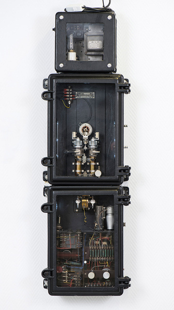 Original URAS device, interior view: emitter and motor at the top, cells and receiver in the middle, electronics at the bottom. Source: BASF SE, used with kind permission.
| Year | Event | Source |
|---|---|---|
| 1913 | Pfeifenanalysator (N₂/H₂ ratio, ammonia synthesis): first patented process analyzer, BASF | AJ History (after BASF) |
| March 1938 | Patent filed for the URAS by Lehrer and Luft, DRP 730478 | AJ History (after BASF) |
| after 1945 | URAS devices in the USA and England, copied by Perkin-Elmer and Beckman, among others | AJ History (after BASF) |
| from 1957 | K. F. Luft develops the UNOR with a two-layer receiver at the Steinkohlenbergbauverein in Essen for CO measurement underground | Schmidt 2003 |
| February 1962 | First prize in a European Coal and Steel Community competition on mine safety, manufacturing licence to Maihak | Schmidt 2003 |
| 1963/64 | UNOR 2 for CO, CO₂ and CH₄ | Schmidt 2003 |
| 1968 | 850 URAS devices in use at BASF alone | AJ History (after BASF) |
| 1986 | 1,122 URAS devices built in total, the most widely used analyzer of its time | BASF |
| 1988 | Gas-filled calibration cells replace test gas cylinders for calibration (manufacturer claim) | ABB |
| 1996 | URAS technology as the basis of the modular Advance Optima series, first network-capable analyzer with its own IP address (manufacturer claim) | ABB |
The timeline is an excerpt from publicly available sources and makes no claim to completeness. The unit numbers of 1968 (in use at BASF) and 1986 (built in total) measure different things. Analytic Journal evaluates manufacturers and devices editorially independently.
The principle itself has changed little in this time. What has changed are the electronics, calibration aids, communication and documentation. This is exactly where the weak point of today's replacement lies.
Why the physics favours SIL
In NDIR, physics determines selectivity: the absorption in the chosen band and, depending on the design, the gas fill in the detector or the interference filters. In none of the designs described above is there a statistical model that first calculates a concentration from spectra. The measured value follows from the detector signal and the calibration.
That makes the device traceable. A malfunction can be followed along the signal path, and the function can be demonstrated on the device itself with test gases. For a safety assessment under IEC 61508 and IEC 61511 this is an advantage, because failure modes and test procedures can be described concretely.
| Feature | NDIR analyzer (classical design) | NIR / FT-NIR with calibration model | Inline Raman with chemometrics |
|---|---|---|---|
| Where does selectivity come from? | Detector gas fill and filter cells (hardware) | Spectrum plus calibration model (software) | Spectrum plus calibration model (software) |
| Evaluation logic | simple, from detector signal and calibration | Spectrometer, computer, chemometrics software | Chemometrics, usually on Windows-based spectrometer software |
| Function check | Zero and test gas on the device | Reference material, standard samples, model validation | Reference measurements and model validation |
| Typical role in the process industry | Gas analysis, also in safety functions | Control, reaction and quality monitoring | Reaction monitoring |
| Publicly verifiable SIL documentation | Examples exist (safety manual)* | not known to the author | not readily SIL-suitable as things stand |
* "Verifiable" does not mean "automatically suitable". SIL is a property of the specific device, its configuration and its proof-test procedure, not of the measuring principle. The selection of features and the classification are an editorial assessment.
An example from documentation practice: the safety manual of an IR gas analyzer certifies the hardware to IEC 61508 and IEC 61511-1 for SIL 1. The only safety function counted there is the analog 4–20 mA output for threshold monitoring; the relay serves for diagnostics only. The manufacturer recommends at least an annual proof test, with a two-point calibration and, in the extended variant, a test gas measurement.
Such statements differ from device to device. Anyone operating or replacing a device in a safety function needs the documentation for exactly this type and configuration.
There is a dedicated technical report for analyzers in safety functions, IEC TR 63176:2019. It gives guidance on planning, installation and operation including maintenance, and adds analyzer-specific points to the general requirements.
From the user side, NAMUR recommendation NE 146 covers process analysis technology systems as part of process control safety equipment. It relates existing experience with process analytical measuring equipment as the sensor part of safety instrumented systems to the existing standards. NE 130 complements this for the selection of field devices for safety instrumented systems taking prior use into account.
For process analysers, prior use is the more practical route. Certified failure rates from a manufacturer's analysis are rare in this device segment, and without documented faults and proof-test results from your own plant there is no basis for that argument. This makes maintenance records part of the safety evidence rather than merely good practice.
Differentiation: software is not excluded, NDIR is not automatically safe
Spectroscopy with software is not unsuitable for SIL in principle. It is more laborious to qualify, because model validity, calibration transfer, drift, interferences, software versioning and validation become part of the proof.
Conversely, NDIR is not automatically simple and safe. Source, chopper, cell windows, detector, sample conditioning and electronics each have their own failure modes. Traceability eases the analysis, but does not replace the assessment of the probability of dangerous failure (PFDavg), diagnostic coverage and the proof-test strategy.
NIR and FT-NIR: established, but without known SIL evidence
FT-NIR is used in the process industry, in my experience mainly for control and for reaction and quality monitoring. Safety-related use has been discussed. I am not aware of any publicly verifiable, device-specific SIL certifications or safety manuals for FT-NIR analyzers, comparable to those of some NDIR gas analyzers. This is a finding of the author and not proof that they do not exist.
Explosion-protection approvals under ATEX or IECEx do not change this. They concern explosion protection, i.e. the avoidance of ignition sources, and say nothing about failure probability, hardware fault metrics or a SIL proof.
The bottleneck lies less in the spectroscopy than in the evaluation. Calibration model, referencing, model validation and change management would have to become part of the safety proof. A SIL application would therefore today be a project-specific special route rather than the standard case.
Strengths and limits in operation
NDIR is established in gas analysis because the signal path is short and the function can be checked on the device. The limits lie less in the principle than in the components and in the sample conditioning.
| Strength | Corresponding limit |
|---|---|
| Selectivity from the hardware, no calibration model | only infrared-active gases can be measured; O₂, N₂ and H₂ do not absorb |
| Function checkable on the device with zero and test gas | test gases must be stocked and monitored for shelf life |
| Simple, traceable signal path | chopper and radiation source are wear parts |
| Measured value follows directly from the detector signal | a creeping loss of signal is read as a change in concentration |
| Long service life in the field | spare-part supply limits the usable life, not the physics |
The most awkward kind of fault is not total failure. A device that stops is noticed at once. More dangerous is the creeping loss of signal: coated or fogged cell windows, an ageing IR source, a detector fill that weakens over years.
The device reports nothing while this happens. It keeps measuring, only too low. In a safety function this is exactly the dangerous undetected failure that the proof test is meant to reveal. That is why safety manuals state a test interval and not a status indicator.
The second limit sits upstream of the analyzer. Water vapour, dust and condensate in the sample gas falsify the measurement or foul the cell. In my experience the majority of faults sit in the sample conditioning and not in the analyzer.
From practice: old devices, spare devices and colleagues in retirement
Hartmann & Braun analyzers in the installed base
I have seen Hartmann & Braun analyzers still in operation, worked with them and kept replacements ready. Many of these devices are 30 to 35 years old. They used to be maintained by colleagues who still did their own soldering, and most of these colleagues are retired today.
Two gaps arise from this. The first is knowledge: how do you replace a detector, what does the display say in the limit range, what does a chopper motor sound like shortly before failure? The second is material, because parts for devices of this age can often only be obtained from stock.
A UNOR in room air monitoring
A second case shows how operators close that gap. At one plant a room air monitoring system for CO ran with several sampling points, and the main analyzer was an old UNOR. The question put to me was whether the instrument could still be maintained.
My answer was uncomfortable. The instrument is old and was discontinued long ago, the colleagues who used to maintain and above all repair analyzers of this kind are retiring right now, and spare parts for it have not been available for a long time. I was then shown a complete second instrument kept in the store as a replacement.
We checked it in the laboratory and it ran perfectly. Since then the arrangement is this: the spare instrument is tested once a year and the old analyzer keeps measuring. That is not a spare-parts concept but a deliberate decision in favour of a second instrument, and it holds only as long as somebody can test both.
One detail beside the cabinet shows how old the whole assembly is. The sample gas pump fitted there comes from one of the first production series of Bühler Technologies. The manufacturer has already registered an interest in taking it for its museum once the cabinet is dismantled.
Why the durability of new devices is falling (observation and hypothesis)
My observation from practice: new devices often do not last as long as the old ones. As a possible reason I see the lower vertical integration of manufacturers. In the past more was built in-house; today the electronics are mostly bought in.
In addition there are shorter lifecycles for electronic components. Many components are no longer available after a few years, and this carries through to the devices. The problem is well known and does not affect NDIR analyzers alone. Trade articles describe the same mechanism for industrial systems in general: components run out on shorter cycles than the plants they sit in, and discontinuation notices often arrive too late to react (Plant Services 2017; Wevolver 2026, sponsored by a component distributor).
This is an experience and a hypothesis, not a data set. Vertical integration is probably not the only factor: component availability, support duration, repair concept and the manufacturer's obsolescence policy all play a part. Reliable failure statistics across device generations are not available. Whether miniaturisation additionally affects service life is open and is not claimed here.
Replacement plan for old NDIR analyzers
First the reason why such plans often stay in the drawer. As long as the measurement runs and the readings look plausible, rebuilding a complete analyser cabinet is hard to justify in operational terms. That is not negligence; it is the situation in which operators actually decide.
Technically, replacement is rarely the problem. A more modern 19-inch instrument usually fits the same cabinet. The question is not whether a replacement exists, but when the decision is taken and whether it is taken under time pressure.
The following overview is an editorial recommendation. It applies particularly where the device is part of a safety function.
| Measure | Content | Timing |
|---|---|---|
| Record the installed base | Type, year of manufacture, serial number, existing safety documents, installation location, function in the process | immediately |
| Secure knowledge | Document the maintenance knowledge of experienced colleagues before they leave: peculiarities, test routines, typical fault patterns | immediately, while colleagues are available |
| Identify wear parts | IR source, chopper drive, cell windows, detector, sample pump, conditioning, electronic boards | within 12 months |
| Obtain manufacturer commitments | In writing: spare-part and support duration, discontinuation notice periods, repair options | within 12 months |
| Track discontinuation notices | Actively subscribe to the manufacturer's product change and discontinuation notices | ongoing |
| Stock critical spares | Parts with long lead times or no successor, with defined storage conditions | after risk assessment |
| Qualify the successor early | Check safety documents, test procedure, signal behaviour in case of fault and control-system integration | before the failure, not after |
| Assess the change | Replacing a device in a safety function is a change and belongs in the plant's management of change | before the replacement |
The most common mistake in replacement: the new device measures equally well, but the safety documentation, the fault-current behaviour or the test procedure does not match the existing design. This only becomes apparent at commissioning or the first test.
Fields of application
| Field | Typical measuring task | Note |
|---|---|---|
| Ammonia synthesis | CO impurities in process gas | early URAS application at BASF |
| Emission monitoring | CO, CO₂, SO₂, NOₓ in flue gas | established in continuous emission monitoring systems |
| Ship exhaust | Exhaust gas measurement on board | in use according to manufacturer information |
| Road tunnels, mining, medicine | Gas monitoring (components not named in the source) | historical applications according to BASF |
| Threshold monitoring in safety functions* | Alarm or shutdown threshold based on the analyzer output | device-specific SIL proof required |
* "Safety function" describes the purpose of use, not a property of every NDIR device.
Which design for which task
| Measuring task | Suitable design | Note |
|---|---|---|
| One component, threshold in a safety function | classical, or one IR source with beam splitter | device-specific safety documentation required |
| One to a few components, control or monitoring | one IR source with beam splitter | the standard case for today's gas analyzers |
| Several components in the same sample gas | single-beam filter photometer | manufacturer data up to six components |
| Sample gas with a high water vapour or dust load | independent of the design | the decision is made in the sample conditioning, not at the analyzer |
| O₂, N₂ or H₂ as the target component | NDIR not suitable | these gases do not absorb in the infrared; consider paramagnetic, ZrO₂ or thermal conductivity measurement |
The assignment is an editorial recommendation and does not replace case-by-case design.
Standards and regulatory basis
| Standard | Short description | Relevance |
|---|---|---|
| IEC 61508 | Functional safety of electrical, electronic and programmable electronic systems | Basis of the SIL assessment of devices |
| IEC 61511 | Functional safety of safety instrumented systems for the process industry | Operator-side requirements, also for design and changes |
| IEC TR 63176:2019 | Analyzers as part of safety-related systems (technical report) | Guidance on planning, installation, operation and maintenance of analyzers in safety functions |
| NAMUR NE 146 (21.10.2013) | Process analysis technology systems as part of process control safety equipment | User-side view of process analytical equipment as the sensor part of safety instrumented systems |
| NAMUR NE 130 (14.07.2023) | Selection of field devices for safety instrumented systems taking prior use into account | Route for devices without certification to IEC 61508 |
| IEC 62402:2019 | Obsolescence management (edition 2.0, May 2019) | Framework for planning the availability of components and devices over their lifetime |
Note: check current revision status with the respective standards organisations before starting a project. This article names the standards as an entry reference, not as a binding interpretation.
FAQ — Frequently asked questions
What is NDIR gas analysis?
NDIR gas analysis measures the concentration of infrared-active gases via the absorption of infrared radiation in a measuring cell. "Non-dispersive" means that the light is not split into individual wavelengths. Selectivity comes from gas-filled detectors and optical filters.
How does the optopneumatic detector (Luft detector) work?
The optopneumatic detector, also called the Luft detector after its developer, consists of gas-filled chambers filled with the target gas. Absorbed radiation heats the fill gas and creates pressure differences, which are sensed via a membrane or a flow sensor. As a result it responds only to the wavelengths that the target gas itself absorbs.
Are today's NDIR devices still built like the URAS of 1938?
The principle is the same, the design is not. The classical design has two emitters and a receiver with a membrane capacitor. Today's gas analyzers often use one IR source, a beam splitter acting as a filter cell and a two-layer detector with a microflow sensor. Alongside these there are single-beam filter photometers with only one optical path, where a rotating filter wheel provides the selectivity and several components are measured in the same optical path.
What was the UNOR and how does it differ from the URAS?
The UNOR is an NDIR analyzer that K. F. Luft developed from 1957 at the Steinkohlenbergbauverein in Essen for CO measurement underground. Unlike the URAS it manages with a single beam path and without a reference cell. Selectivity comes from a two-layer receiver whose two chambers, placed one behind the other, absorb the centres and the flanks of the absorption lines differently; the chamber lengths are chosen so that cross-sensitivity is minimised. After the patent expired, Siemens and Hartmann & Braun adopted this receiver principle.
What is the difference between NDIR and NIR, FT-NIR or Raman?
NIR, FT-NIR and Raman generate spectra and convert them into concentrations via a calibration model (chemometrics). NDIR obtains its selectivity from the hardware and delivers a single measurement signal. This makes the evaluation simpler and the function traceable on the device, but does not replace a safety assessment.
Why is NDIR used in safety-related applications?
Because selectivity and evaluation are physically determined and simple, failure modes and test procedures can be described concretely. There are NDIR-based analyzers whose hardware is assessed to IEC 61508 and IEC 61511, for example for SIL 1. SIL suitability is always device-specific and must be demonstrated with the documents of the specific type.
Are there SIL-certified FT-NIR analyzers?
The author is not aware of any publicly verifiable, device-specific SIL certifications or safety manuals for FT-NIR analyzers. FT-NIR is used in the process industry mainly for control and quality monitoring. Explosion-protection approvals under ATEX or IECEx concern explosion protection, not functional safety.
Which standards apply to NDIR analyzers in safety functions?
The basis is IEC 61508 for the devices and IEC 61511 for use in the process industry. IEC TR 63176 gives guidance specifically for analyzers in safety functions, and IEC 62402 helps with obsolescence management. From the user side, NAMUR NE 146 covers process analytical systems and NE 130 the selection of field devices taking prior use into account. The SIL level achieved is stated in the manufacturer's safety documentation.
How do you notice that an NDIR analyzer is drifting out of true?
Usually not on the device itself, because a slow loss of signal produces no error message. Coated cell windows, an ageing radiation source or a weakening detector fill lower the reading without any diagnostic responding. This is why fixed test intervals and test gas are used rather than status indicators. In safety functions this is the reason for the prescribed proof test.
How long do NDIR analyzers last?
There is no blanket figure. In practice, devices from the 1980s and 1990s still run if they are maintained and spare parts are available. For newer device generations no reliable comparison data exist; here the written support and spare-part commitment of the manufacturer matters most.
Why is replacement planning so critical for old analyzers?
Old devices are often part of a safety function and cannot simply be replaced by a different type. Maintenance knowledge is lost when experienced colleagues retire, and spare parts become scarce. Anyone who only plans at the point of failure has to qualify a new device under time pressure.
What are typical mistakes when replacing an NDIR analyzer in a safety function?
Often only the measuring range and gas component are compared. Safety documentation, signal behaviour in case of fault and the test procedure are not checked. In addition, the replacement is often not treated as a change in the plant's management of change.
What this article deliberately does not cover
Specific device comparisons and manufacturer ratings This article remains manufacturer-neutral. A market overview of current NDIR analyzers is a separate, editorially labelled format.
A market overview is planned as a separate topic for a future Analytic Journal article, currently without a fixed date.
Sample conditioning and sample gas path The influence of water vapour, dust and condensate on the measurement is a practical topic of its own with its own structure.
Sample conditioning for gas analyzers is also planned as a separate topic for a future article, currently without a fixed date.
Qualifying chemometric methods for safety functions How calibration models, referencing and model validation could be integrated into a SIL proof is a topic of its own.
This topic is conceivable as a separate Analytic Journal article, currently without a fixed date.
Documented service-life data Whether and how service life and component availability have changed across device generations is described here as an observation, not backed by data. An evaluation of failure and discontinuation data would be a project of its own.
Conclusion
In NDIR, physics determines the measurement, and that eases the safety argument. Methods with a calibration model such as FT-NIR or Raman are therefore not excluded, but harder to qualify. SIL suitability remains in every case a property of the specific device and its documentation. The greater risk today lies in replacement: fading maintenance knowledge, scarce parts and devices whose electronics have shorter lifecycles.
Sources
1. Standards and guidelines
| Standard | Short description | Relevance |
|---|---|---|
| IEC 61508 | Functional safety of E/E/PE systems | SIL basis |
| IEC 61511 | Functional safety, process industry | Application and changes |
| IEC TR 63176:2019 | Analyzers in safety-related systems | Planning, operation, maintenance |
| NAMUR NE 146 (21.10.2013) | Process analysis technology in safety instrumented systems | User recommendation |
| NAMUR NE 130 (14.07.2023) | Field device selection with prior use | User recommendation |
| IEC 62402:2019 | Obsolescence management | Availability planning |
2. National / industry standards
- NAMUR NE 146, "Process Analysis Technology Systems as Part of Process Control Safety Equipment", version 21.10.2013 (title and version per the NAMUR publication notice; the full text was not available for this article).
- NAMUR NE 130, "Selection of field devices for safety instrumented systems taking prior use into account", edition 14.07.2023, replacing the version of 16.09.2011 (title and edition per the NAMUR publication notice).
3. Technical literature
- BASF: "Infrarot-Spektroskopie", article in the "Herzstück" series on the development of the URAS. Describes developers, year, applications and the unit count up to 1986.
- control.com: online textbook "Non-dispersive Luft detector spectroscopy". Explains design, reference cell, chopper, Luft detector and filter cells.
- Stephan Schmidt: "Entwicklung von Zweikomponentenverfahren für die nichtdispersive IR-Spektroskopie (NDIR) mit Hilfe von chemometrischen Methoden", doctoral thesis, Faculty of Natural Sciences, University of Duisburg-Essen (Duisburg campus), 2003. Used for the development history of the UNOR, the two-layer receiver, the 1962 prize, the Maihak licence and the later adoption of the receiver principle by Siemens and Hartmann & Braun.
- Guido Seidel: "Kultivierungen mit einem Hochleistungsstamm von Acremonium chrysogenum in komplexen und synthetischen Medien", doctoral thesis, Institute of Technical Chemistry, University of Hannover, 1999. Used as evidence for the use of a UNOR 6N (Maihak) as a CO₂ detector in bioreactor off-gas analysis.
4. Organisations and data sources
- Analytic Journal: History page on URAS and Pfeifenanalysator, after BASF documentation (BASF SE, used with kind permission; patent DRP 730478, unit count 1968, copies after 1945).
- ABB: "85 years of URAS" (manufacturer page, used only for the manufacturer claims on 1988 and 1996).
- IEC Webstore: entry for IEC 62402:2019 (title, edition, publication date).
- BSI Knowledge: entry for PD IEC TR 63176:2019 (title, publication date, scope).
- Siemens Support: safety manual of an IR gas analyzer (example of the structure of SIL documentation: safety function, test interval, fault current ranges).
- Siemens: device manual of a current NDIR analyzer, Ultramat 6 (manufacturer document, used for the present-day design: one IR source, beam splitter acting as a gas-filled filter cell, two-layer detector with microflow sensor).
- HORIBA: manufacturer page "Structure and Operating Principle of Gas Analyzer Using NDIR" (overview of pneumatic and pyroelectric detectors and single-beam methods).
- SICK: product documentation for the MCS300P process photometer (non-dispersive photometric method, heated cell, filter wheels, up to six components with dynamic cross-sensitivity correction).
- ABB: product page for the PIR3502 infrared photometer of the Multiwave range (filter wheel with up to eight wavelengths, ranges 800–2800 nm and 2.5–14.5 µm).
- Wikipedia: "Nondispersive infrared sensor" (overview of principle and typical gases).
- Plant Services: Will Jacobsen, "Avoid the agony of obsolete parts", 14 March 2017 (shorter component lifecycles, rising discontinuations; general for industrial systems, not NDIR-specific).
- Wevolver: Jake Hertz, "Preserving Industrial Systems While Preparing for What Comes Next", 8 January 2026 (plants with decades of service life, components with shorter cycles; sponsored by Rochester Electronics, a distributor, therefore used for the mechanism only).
© 2026 Analytic Journal / Dusko Kadijevic. All rights reserved.
This article is protected by copyright. Short excerpts with attribution and an active link to analyticjournal.com are permitted. Full or substantial reproduction, including in digital form, by AI systems or automated processes, is not permitted without the express written consent of the publisher. Enquiries: info@analyticjournal.de
Analytic Journal — The Portal for Process Analytics
Check standards for current revision status before starting a project.
Further topics on Analytic Journal:
Dusko Kadijevic | Publisher Analytic Journal | analyticjournal.com
Written October 2026. All content formulated in our own words, created with AI assistance.
Erstveröffentlicht am 8. Juni 2026 auf analyticjournal.com