Analytic Journal is growing – your feedback shapes the platform.Send feedback
Gas Analysis
Fixed and Portable Gas Detection Systems: Personnel Protection, Process Protection and Leak Monitoring
Category: Gas Analytics | Occupational Safety | Explosion Protection | Process Monitoring | PAT
Author: Dusko Kadijevic, Publisher Analytic Journal
Written: May 2026
Last updated: October 2026
Reading time: approx. 12 minutes
Target audience: Process engineers, safety officers, plant designers, instrumentation engineers at permitted industrial facilities in the UK, US and Canada
Definition
Gas detection systems are instruments for continuous or periodic monitoring of gas concentrations in ambient air or process spaces — with the objective of detecting hazardous concentrations at an early stage and triggering protective actions. They serve personnel protection (protection against toxic gases, oxygen deficiency or explosion hazard), process monitoring (leak detection, plant surveillance) or both.
The distinction between portable devices and fixed systems is not merely a question of form factor — it determines the intended use, measurement interval, regulatory requirements and the nature of the protective actions that follow an alarm.
Regulatory requirements differ between the UK, US and Canada; see “Regulatory Framework: UK, US and Canada” further below. German BG RCI guidance (T 021/T 023) is used as a reference example only and is a recommendation, not binding law.
Personnel Protection vs. Process Protection — Two Different Logics
A fundamental misunderstanding in practice: personnel protection and process monitoring are frequently approached with the same devices and the same logic. This leads to problems.
| Characteristic | Personnel Protection | Process Protection / Leak Monitoring |
|---|---|---|
| Objective | Protect persons from hazardous exposure | Detect leaks, process deviations |
| Typical device | Portable personal gas monitor | Fixed gas detection system, with sampling where needed |
| Alarm trigger | Immediate protective action (evacuation) | Process control, maintenance initiation |
| Regulatory framework | DSEAR/UKEX (UK), OSHA/NFPA (US), CSA/Provincial OHS (CA) | Site-specific permit conditions + above |
| Typical inspection / calibration interval | Bump test before each deployment or shift; calibration per manufacturer and site procedure | Per manufacturer, documented maintenance strategy and applicable requirements |
| Sensor lifetime | Limited — portable devices have smaller sensors | Longer — fixed systems accommodate larger sensors |
Measurement Principles in Gas Detection
Electrochemical Sensors
Principle: The target gas is oxidised or reduced at an electrode. The resulting current flow is proportional to gas concentration.
Typical target gases: CO, H₂S, NO₂, SO₂, Cl₂, NH₃, HCN, O₂
Strengths: Low cost, compact, proven technology, fast response time.
Limitations — cross-sensitivity as critical weakness:
Electrochemical sensors frequently respond not only to the target gas but also to chemically similar compounds. The most widely known example: CO sensors and acetylene (C₂H₂).
Practical note from the field — CO sensor responding to acetylene from a neighbouring facility: During a plant shutdown, the responsible project engineer called me. The portable CO monitors carried by colleagues were triggering alarms repeatedly, with no identifiable CO source. The cause was acetylene released by a neighbouring operation — with its own permit, entirely legally. The electrochemical CO sensors were responding to it as a cross-sensitivity.
In the course of that conversation, something occurred to the engineer: he had just ordered fixed electrochemical CO sensors. They were intended to replace the existing NDIR system with extractive sampling used for ambient air monitoring. Commercially the decision was understandable — individual sensors cost less than a photometer with pump, valves, sample lines and sample conditioning. At this location, however, they would have had exactly the same problem as the portable devices. He reached the conclusion himself: these sensors are not suitable for this location.
The sensors were deployed elsewhere, and the NDIR system was retained and expanded instead. In this case NDIR was more selective and distinguished CO from acetylene. Why NDIR had originally been chosen was written down nowhere. That very acetylene had been the reason.
The lesson: before selecting or replacing a gas detection system, the entire surrounding environment must be analysed — not just the operator's own plant. And the rationale for a measuring principle belongs in the documentation, otherwise it is lost at the next replacement.
Pressure dependence of electrochemical sensors:
Practical note — calibration failure due to incorrect test gas pressure: A contractor built a process monitoring cabinet with electrochemical sensors. During commissioning, neither zero-point adjustment nor span calibration to target concentration worked correctly. The error: the contractor supplied test gas through an injector while the gas cylinder was under elevated pressure. Electrochemical sensors are highly sensitive to pressure changes — elevated gas pressure directly distorts the measurement. When the test gas was supplied at the same conditions as in operation — same pressure, same flow rate — calibration worked correctly. The lesson: when calibrating electrochemical sensors, test gas conditions must closely match operating conditions, and the manufacturer's test gas procedure must be followed.
Lifetime: Electrochemical sensors have a limited service life by design, typically 1–3 years depending on the gas. End of life often arrives abruptly rather than gradually — which is why routine response checks matter.
Catalytic Sensors (Pellistor)
Principle: Flammable gases combust on a catalytically active wire. The resistance change from heating is proportional to gas concentration.
Typical target gases: Flammable gases and vapours (methane, propane, hydrogen, solvents)
Strengths: Proven, cost-effective, widely used in explosion protection.
Critical limitations:
Oxygen requirement: Catalytic sensors require oxygen to function — the overview table in BS EN 60079-29-2 (reproduced in the German guidance T 023) lists a minimum of around 10 % oxygen in the gas sample. In inerted areas or at very high gas concentrations (above the UEL), they will not provide a valid flammable-gas reading. This must be considered in device selection and test gas composition — a test gas in pure nitrogen produces no signal from a pellistor.
Sensor poisons: Silicone compounds, sulphur compounds and certain halogenated compounds can permanently poison and deactivate the catalyst — the sensor then shows no response even when gas is present.
Inspection and calibration intervals: Catalytic sensors have no recognised self-diagnostics, so they are checked externally at intervals set by the manufacturer's specification, the site's maintenance strategy and applicable requirements — in practice more often than self-monitoring optical systems.
Optical Sensors (IR, NDIR, TDLS)
Principle: Infrared or laser light passes through the measurement gas. Gas absorption is used to calculate concentration.
Typical target gases: CH₄, CO, CO₂, hydrocarbons (NDIR), specific gases (TDLS)
Strengths: Lower chemical cross-sensitivity, no catalyst poisoning risk, and integrated self-diagnostics: infrared instruments can monitor light source failure and excessive loss of detector signal due to contamination. Where manufacturer and applicable standard permit, annual functional testing may be sufficient.
Limitations: Higher capital cost, not available for all gas types, contamination of optical surfaces must be managed. Lower chemical cross-sensitivity does not mean no cross-sensitivity: spectral interferences — overlapping absorption bands, water vapour, gas matrix effects — must still be assessed. And self-diagnostics cover specific failure modes only; they do not replace system-level checks of alarm functions or an assessment of suitability for the location.
Semiconductor Sensors (Flammable Gases)
Scope: Semiconductor sensors are listed as a measuring principle for flammable gases in Table 1 of the German guidance T 023 (taken from EN 60079-29-2). This section therefore refers to flammable gases. The details below are taken from that table.
Principle: The gas changes the electrical conductivity of a semiconductor layer; the change is used as the measurement signal.
Typical measuring range: up to the LEL.
Oxygen requirement: Oxygen in the gas sample is not required according to T 023 (shown in brackets; see the standard for details).
Critical limitations: Non-flammable gases and humidity can influence the reading; SO₂ and NOₓ are named. Poisoning is possible from silicone, halogenated compounds and SO₂. The response time depends on the substance. After a measuring-range overload, zero and sensitivity may have changed permanently (see the inspection and calibration intervals below).
Inspection intervals: The guidance does not name an assessed self-diagnostic for semiconductor sensors, so they are checked externally at the usual intervals.
Other measuring principles: Table 1 of T 023 additionally lists thermal conductivity sensors, photoionisation detectors, flame ionisation detectors, flame temperature analysers and paramagnetic oxygen sensors. They are not covered in this article.
Sensor Comparison for Practice
| Property | Electrochemical | Catalytic (Pellistor) | Optical (IR/NDIR/TDLS) | Semiconductor |
|---|---|---|---|---|
| Typical target gases | Toxic gases, O₂ | Flammable gases | CH₄, CO, CO₂, flammable HC | Flammable gases (up to LEL) |
| Cross-sensitivity | High — must be checked carefully | Medium | Low chemical; spectral interferences must be assessed | Affected by non-flammable gases and humidity (SO₂, NOₓ) |
| O₂ requirement | Yes (O₂ sensor) / No (others) | Yes — mandatory (about ≥ 10 %) | No | No (per T 023) |
| Sensor poisons | Conditional | Yes — silicone, sulphur | No | Yes — silicone, halogens, SO₂ |
| Pressure dependence | High | Medium | Low (NDIR), compensable (TDLS) | not documented |
| Self-diagnostics | None | None | Yes — for specific failure modes | Not named in the guidance |
| Typical inspection / calibration interval | Shorter | Shorter | Annual may be sufficient where permitted | Shorter |
| Capital cost | Low | Low | Higher | not documented |
| Sensor lifetime | Limited (1–3 years) | Limited | Longer | not documented |
Sensor Positioning — Where Does the Sensor Actually Measure?
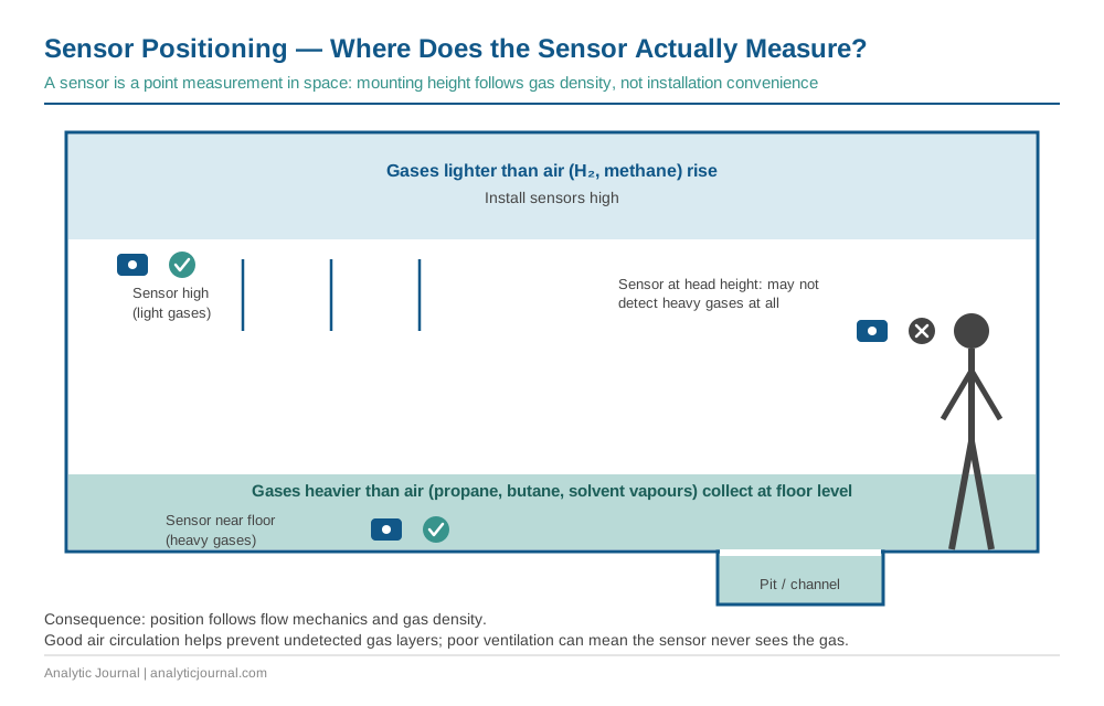
A frequently underestimated aspect: a sensor is a point measurement in space. It only measures at the location where it is installed. Gas that occurs elsewhere or distributes differently than expected may not be detected — or detected too late.
Gases heavier than air — a common error:
Many flammable gases and vapours — propane, butane, many solvent mixtures — are heavier than air and behave more like a liquid. They accumulate at floor level, in pits, channels and low-lying areas. A sensor installed at head height may not detect these gases at all — the gas flows undetected along the floor.
Gases lighter than air — H₂, methane — rise upward. Sensors must be installed correspondingly high.
Consequence: Sensor positioning must be derived from the flow mechanics and gas density — not from practical installation convenience. Good air circulation in the facility can help prevent gas layers from building up undetected. Poor ventilation can mean a sensor never detects the gas it is supposed to detect.
Airflow and leak sources: Sensor placement is also shaped by room airflow. Near exhaust ducts or supply air openings, a draught can carry gas past the sensor or dilute it before it is detected. Conversely, sensors are often placed deliberately where air flows anyway, such as at ventilation ducts or extraction points, to catch escaping gas. In addition, sensors should sit close to likely leak sources: pumps, seals, flanges and pipe connections. This is where the largest leak is to be expected and the path to the sensor is shortest.
Portable Gas Detection Systems — Operational Considerations
Test Before Every Deployment
It is common industry practice, and a minimum requirement of many manufacturers and site procedures, to bump test portable gas detection systems before each deployment or at the start of each working day. This is not a formality — it is the only way to confirm the sensor still responds. Electrochemical sensors in particular have a limited service life and can degrade without visible indication. As a German example, BG RCI guidance T 021/T 023 recommends a visual check and display test before every work shift.
Bump test: The device is briefly exposed to test gas — it must show an alarm response. The operator defines a pass criterion. This is not a calibration procedure but a functional verification. Checking zero in ambient air alone is not a valid bump test.
Sensor Lifetime in Portable Devices
Portable devices have smaller sensors than fixed systems by design — space is limited. Smaller sensors have shorter service lives. Some manufacturers offer larger electrochemical sensors in portable devices — these last longer and are better suited to intensive operating conditions. This is a selection criterion frequently overlooked in practice.
Catalytic Sensors and O₂ — a Critical Point
Catalytic sensors require oxygen to function. In inerted areas or areas with low O₂ content, they produce no signal — even when flammable gas is present. This is a potentially life-threatening error when a user relies on the pellistor without knowing that oxygen deficiency deactivates the measurement.
When using test gas for catalytic sensors: the test gas must contain sufficient oxygen. A test gas in pure nitrogen or with very low O₂ content produces no or a falsified signal from the pellistor — the sensor appears functional when it would not be under real conditions.
Terminology Used in This Article
Four terms are constantly mixed up in practice. This article uses them as follows:
- Bump test: a brief exposure of the instrument to test gas to confirm that it responds and alarms. It is a functional response check, not a calibration.
- Calibration: comparison of the instrument reading with a known test gas concentration, without adjusting.
- Adjustment: setting zero and span after a calibration has shown a deviation. It is a separate step.
- Inspection: visual and functional check of the instrument and its accessories (inlet, sampling line, status indications).
Fixed Gas Detection Systems — Specific Considerations
Diffusion vs. Aspirated Systems
Fixed systems can be designed as diffusion systems (gas diffuses to the sensor) or aspirated systems (sample air is actively drawn in).
| Characteristic | Diffusion | Aspirated |
|---|---|---|
| Response time | Slower | Faster |
| Sampling | Passive — depends on air movement | Active — defined sample path |
| Selective sampling | Not possible | Possible (e.g. from specific areas) |
| Maintenance | Lower | Higher (pump, filter, lines) |
| Suited for | Area monitoring, simple applications | Leak detection, aggressive gases, NDIR systems |
For aspirated systems, the sampling line, filters and flow rate are part of the measuring chain: line length and discontinuous sampling add to the time to alarm, and adsorption or condensation can distort the reading.
Inspection and Calibration Intervals
Inspection and calibration intervals must follow the manufacturer's specification, the site's documented maintenance strategy and the applicable regulatory or contractual requirements. Intervals of several months are common for electrochemical and catalytic sensors; optical sensors with self-diagnostics may be checked less often where permitted. None of this is a universal standard requirement, and in the UK, US and Canada the interval is usually defined by the manufacturer and the site's risk assessment rather than by a single published number.
Example from Germany — how a regulator-backed guideline structures it. The BG RCI guidance T 021/T 023 (October 2023) is a recommendation, not binding law, and it can be deviated from if equivalent safety is demonstrated in the risk assessment. It recommends maximum intervals of one month for visual checks (portable devices: before each work shift), four months for functional checks (up to one year where an assessed self-monitoring function is in place), and one year for system checks.
More useful than the numbers is the logic for entering those maximum intervals. Where there is no sufficient experience with the application, the guidance asks for two functional checks four weeks apart after commissioning, then checks every two months, and only then the maximum interval — each step provided no readjustment was necessary. If readjustment is needed within the first eight weeks, the intervals are shortened, and if they become unreasonably short, a better suited measuring principle should be considered. In other words: start tight, extend while the device proves stable, step back when it does not. That approach transfers well to any jurisdiction, provided it is documented in the site's maintenance strategy.
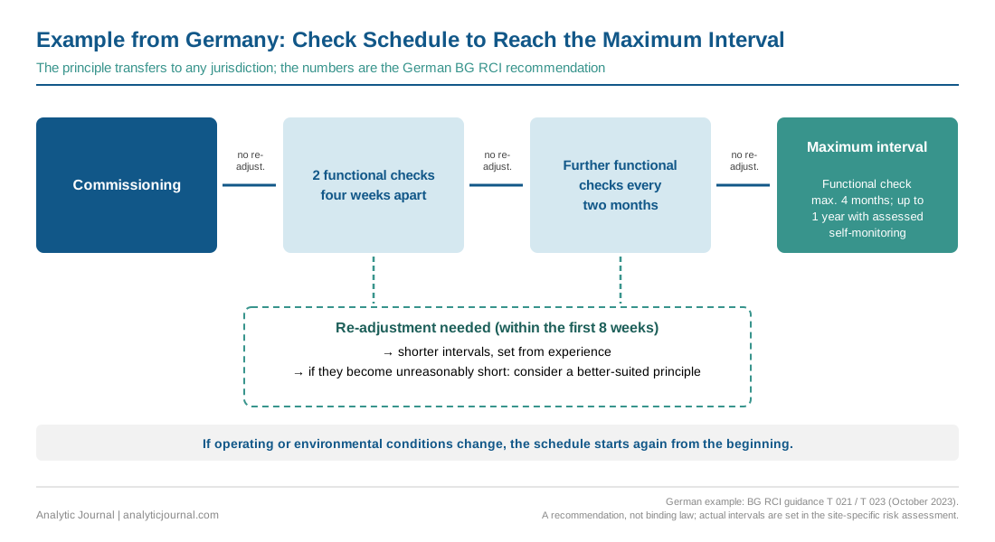
Extending an interval requires evidence that the safety function is not compromised; shortening it does not.
Alarm Concepts and Threshold Values
Alarm levels and the actions they trigger must be defined in the site-specific risk assessment and alarm philosophy. The values below are orientation, not universal rules. In general, thresholds must be low enough for protective actions to take effect in time, and high enough to avoid frequent false alarms, which lead to alarm fatigue.
Toxic Gases — Relationship to Exposure Limits
For toxic gases, alarm thresholds are referenced against occupational exposure limits. They are commonly based on a fraction of the applicable limit, but the actual values, averaging times and responses must be set in the site-specific exposure assessment.
United Kingdom (HSE EH40):
- WELs are legally enforceable under COSHH and provide TWA and STEL values. Pre-alarm and main alarm levels are typically derived from these, with the exact setpoints defined by the site's alarm philosophy.
United States (OSHA PELs / ACGIH TLVs):
- OSHA PELs are legally enforceable minimum standards — many are outdated (set in 1971)
- ACGIH TLVs are more current and widely used as best practice benchmarks, but they are not legally binding limits in the US
Canada — Ontario (Regulation 833):
- OELs follow the Ontario Table or the 2017 ACGIH TLV table where no Ontario value exists
- TWA (Time-Weighted Average) and STEL (Short-Term Exposure Limit) values apply
- Example: CO TWA = 25 ppm (Ontario/ACGIH); alarm thresholds are set accordingly
- Always verify current values at ontario.ca — the table is updated periodically
Flammable Gases — Relationship to LEL
For flammable gases, alarm thresholds are referenced against the Lower Explosive Limit (LEL) — equivalent to UEG (Untere Explosionsgrenze) in German. Typical practice places alarms between about 10 % and 40 % LEL. German guidance T 023 explicitly advises against setting alarm thresholds above 40 % LEL. The site's alarm philosophy governs the actual setpoints.
Oxygen
Typical practice: an oxygen-deficiency alarm at or below about 19.5 vol% and an oxygen-enrichment alarm above 23 vol% (increased fire hazard). As a German example, T 021 uses 19 vol% (pre-alarm) and 17 vol% (main alarm) for oxygen deficiency, and typically below 19 vol% and above 23 vol% where both directions are monitored. Confined-space and occupational safety rules for the jurisdiction may define different values — confirm what applies. For inerted areas and process atmospheres there are no universal recommendations; alarm thresholds must keep a sufficient margin from the limiting oxygen concentration.
Regulatory Framework: UK, US and Canada
United Kingdom
In the UK, gas detection for hazardous area applications is governed by:
- DSEAR (Dangerous Substances and Explosive Atmospheres Regulations 2002) — requires employers to assess and control risks from flammable gases and vapours
- UKEX (UKCA marking for equipment in potentially explosive atmospheres) — in Great Britain, equipment for explosive atmospheres is certified under the UKEX regime. Since 1 October 2024 (SI 2024/696), recognition of the CE marking (ATEX) in Great Britain has been extended indefinitely: manufacturers may use either the UKCA or the CE marking, depending on the product category. Northern Ireland continues to follow EU rules
- BS EN 60079-29-2 — selection, installation, use and maintenance of gas detectors for flammable gases
- BS EN 62990-1 — performance requirements for toxic gas detection systems
- EH40/2005 Workplace Exposure Limits (current edition) — published by HSE, legally enforceable under COSHH Regulations. Provides TWA and STEL values for hazardous substances
Key reference: The HSE EH40 table is the UK equivalent of the German TRGS 900 — it defines the exposure limits against which alarm thresholds for personnel protection applications are set.
United States
In the US, gas detection requirements arise from multiple regulatory frameworks:
- OSHA 29 CFR 1910.119 (PSM) — Process Safety Management for highly hazardous chemicals; requires gas detection as part of the process hazard analysis
- OSHA 29 CFR 1910.1000 (PELs) — Permissible Exposure Limits for air contaminants in general industry
- NFPA 72 — National Fire Alarm and Signalling Code, covers gas detection systems integrated into fire alarm systems
- API RP 505 — Recommended practice for the location and installation of fixed flame and gas detection systems in the petroleum industry
- UL 2075 — Standard for Gas and Vapour Detectors and Sensors
- UL 60079-29-1 — Performance requirements for flammable gas detectors in hazardous locations (US harmonised version of IEC 60079-29-1)
Hazardous area classification in the US follows the Class/Division system (Class I Division 1/2, Groups A–D) — different from the European Zone system (Zone 0/1/2) used in ATEX and IECEx. Modern US installations increasingly use the Zone system as an alternative; both are recognised under NEC Article 505.
Canada
Canada operates a dual framework:
- CSA C22.2 No. 60079-29-1:2017 (Amendment 1:2022) — current standard for flammable gas detectors in hazardous locations, based on IEC 60079-29-1. This superseded the older CSA C22.2 No. 152-M1984
- CSA C22.2 No. 60079-11:14 (R2022) — intrinsic safety requirements, covering both Zone and Division markings
- IEC/CSA/UL 62990-1 — toxic gas detector performance requirements
- Provincial OHS legislation — occupational exposure limits (OELs) are set at provincial level. Ontario's OELs are defined under Regulation 833 (Control of Exposure to Biological or Chemical Agents), which references both the Ontario Table and the 2017 ACGIH TLV table. Other provinces follow similar structures.
Important note on Canadian OELs: The Ontario OEL table (Regulation 833) is updated periodically. Always verify current values at ontario.ca — the ACGIH TLV table incorporated by reference is updated annually. The same applies to other provinces: British Columbia, Alberta and Quebec each maintain their own OEL regulations.
Class/Division vs Zone in Canada: Like the US, Canada uses both the traditional Class/Division system and the Zone system. CSA C22.2 No. 60079-11:14 explicitly addresses both markings for intrinsically safe equipment, covering both Division and Zone classification in a single standard.
Standards and Regulatory References
| Standard / Regulation | Region | Content |
|---|---|---|
| BS EN 60079-29-2 | UK / EU | Selection, installation, use and maintenance of flammable gas detectors |
| BS EN 62990-1 | UK / EU | Performance requirements for toxic gas detection systems |
| DSEAR 2002 | UK | Dangerous Substances and Explosive Atmospheres Regulations — risk assessment framework |
| UKEX / ATEX 2014/34/EU | UK (GB) / EU | Equipment for explosive atmospheres; since 1 October 2024 CE marking is recognised in GB indefinitely alongside UKCA (SI 2024/696) |
| EH40/2005 (current edition) | UK | Workplace Exposure Limits — HSE, enforceable under COSHH |
| UL 60079-29-1 | US | Performance requirements for flammable gas detectors — hazardous locations |
| UL 2075 | US | Standard for gas and vapour detectors and sensors |
| NFPA 72 | US | National Fire Alarm and Signalling Code — gas detection integration |
| API RP 505 | US | Fixed flame and gas detection in petroleum industry |
| OSHA 29 CFR 1910.119 | US | Process Safety Management — gas detection requirements |
| OSHA 29 CFR 1910.1000 | US | Permissible Exposure Limits for air contaminants |
| CSA C22.2 No. 60079-29-1:2017/A1:2022 | Canada | Flammable gas detectors — current standard |
| CSA C22.2 No. 60079-11:14 (R2022) | Canada | Intrinsic safety — Zone and Division markings |
| IEC/CSA/UL 62990-1 | North America | Toxic gas detector performance — current standard |
| Ontario Regulation 833 | Canada (ON) | Control of Exposure to Biological or Chemical Agents — OELs |
| NEC Article 500/505 | US | Class/Division and Zone classification for hazardous locations |
| BG RCI T 021 / T 023 | Germany (reference example) | Use and operation of gas detection equipment for toxic gases and for explosion protection — recommendations, October 2023 |
FAQ — Frequently Asked Questions
What is the difference between fixed and portable gas detection systems?
Fixed systems are permanently installed in facilities and provide continuous monitoring — typically used for area surveillance, process monitoring and leak detection. Portable devices are carried by personnel and provide personal protection during entry into potentially hazardous areas, maintenance operations or inspections. The regulatory requirements, calibration intervals and alarm response differ significantly between the two.
Why does my CO sensor alarm when no CO is present?
Electrochemical CO sensors have cross-sensitivities — they respond to other chemically similar gases. Acetylene is one of the most common causes of false alarms in CO sensors. If neighbouring operations use or release acetylene, this can trigger alarms in CO sensors. The solution is either a more selective measurement principle (NDIR, TDLS) or a thorough analysis of surrounding gas sources before device selection. The same applies in reverse: before replacing an existing measurement, establish why that measuring principle was chosen in the first place — the reason is often a cross-sensitivity that is no longer documented anywhere.
Why does my electrochemical sensor calibration fail?
Electrochemical sensors are sensitive to pressure changes. If test gas is supplied at a different pressure than the operating measurement gas — for example directly from a pressurised cylinder without pressure reduction — this distorts the calibration. Test gas must reach the sensor under the same conditions as the measurement gas in operation — same pressure, same flow rate.
Where should sensors for gases heavier than air be installed?
Gases heavier than air — propane, butane, many solvent vapours — accumulate at floor level, in pits and low-lying areas. Sensors for these gases must be installed close to the floor. A sensor at head height may not detect a heavy gas at all — it flows undetected along the floor.
Why does my catalytic sensor produce no signal during the function test?
Catalytic sensors require oxygen to function. If the test gas contains no or insufficient oxygen — for example when test gas is in pure nitrogen — the sensor produces no signal. Test gas for catalytic sensors must contain sufficient oxygen. The same applies in inerted areas: catalytic sensors will not provide a valid flammable-gas reading in inert atmospheres.
How often must gas detection systems be tested?
There is no single answer. Inspection and calibration intervals must follow the manufacturer's specification, the site's documented maintenance strategy and the applicable regulatory or contractual requirements. Optical sensors with self-diagnostics may be tested less often where permitted. As a German example, BG RCI recommends maximum intervals of four months for functional checks (up to one year with assessed self-monitoring) and one year for system checks, with a staged start-up programme of tight checks that are extended as the device proves stable. Portable devices should be bump tested before each deployment.
What is the difference between a bump test, a calibration and an adjustment?
A bump test is a brief exposure to test gas to confirm the instrument responds and alarms. A calibration compares the reading with a known test gas concentration without changing it. An adjustment sets zero and span and is only needed when the calibration shows a relevant deviation.
What is the difference between UKCA and CE/ATEX marking for gas detectors?
ATEX (2014/34/EU) is the European equipment certification for explosive atmospheres. In Great Britain the equivalent is the UKEX regime with UKCA marking. Since 1 October 2024, recognition of CE marking in Great Britain has been extended indefinitely, so manufacturers may use either marking, depending on the product category. Northern Ireland continues to follow EU rules. Manufacturers serving several markets should verify the current marking and conformity-assessment requirements for each product.
What is the difference between Class/Division and Zone classification?
Class/Division is the traditional North American hazardous area classification system used in the US (NEC Article 500) and Canada. Class I covers flammable gases and vapours, with Division 1 (normally hazardous) and Division 2 (abnormally hazardous). The Zone system (Zone 0/1/2) is used in ATEX and IECEx and is also recognised in the US (NEC Article 505) and Canada as an alternative. Gas detection equipment must be certified for the applicable classification system used at the specific facility.
Why are optical sensors advantaged for maintenance?
Infrared instruments can monitor their own light source and detector signal, so certain failures — such as a failed source or heavy contamination — are detected without external testing. Electrochemical and catalytic sensors have no comparable recognised self-diagnostics and can degrade without indication, which is why they are checked externally more often. Self-diagnostics cover specific failure modes only, and spectral interferences still need to be assessed.
What This Article Deliberately Does Not Cover
SIL-classified safety instrumented systems incorporating gas detection
The integration of gas detection systems into SIL-classified safety loops per IEC 61511 follows its own requirements and is covered in the separate AJ article on SIL and PFD.
Further reading: "SIL and PFD in Process Analytics — Functional Safety Explained for Practitioners"
Fixed gas measurement systems for CEMS (emissions monitoring)
Gas measurement installations for regulatory continuous emission monitoring follow their own requirements (EN 14181, QAL1/2/3 in Europe; 40 CFR Part 60 Performance Specifications in the US; MCERTS in the UK) and are covered in the separate AJ article on CEMS.
Further reading: "CEMS — Continuous Emission Monitoring in the Process Industry"
Portable and fixed gas detectors in process monitoring
Both portable and fixed gas detectors can also be used for process monitoring. This use follows different requirements than personnel protection and is covered in a separate AJ article.
Summary
Gas detection systems are more than mandatory equipment — properly applied, they are an active safety and process monitoring instrument. The most important lessons from practice:
Sensor selection must account for gas sources across the entire facility and its surroundings — not just the operator's own process chemistry. Cross-sensitivities are the most common cause of false alarms and incorrect decisions.
Sensor positioning follows the physics of the gas — not the convenience of installation. Heavy gases accumulate at the bottom, light gases rise.
Calibration must be performed under conditions that match operation — pressure, flow rate and gas matrix must correspond.
Intervals are a decision, not a number. Start tight, extend while the device proves stable, step back when it does not — and record the reasoning.
Optical sensors with self-diagnostics are the lowest-maintenance and most reliable long-term choice — even if capital costs are higher. Spectral interferences still have to be assessed.
The rationale belongs in the documentation. Why a particular principle was selected is frequently known only to the people involved at the time. The rationale for detector type, location, alarm setpoints, calibration basis and any later change should be part of the safety documentation and the management-of-change process. Otherwise, once the people are gone, the next generation replaces a measurement whose reason for existing nobody can name — and reintroduces a problem that had already been solved.
Regulatory requirements differ significantly between the UK, US and Canada — both in certification frameworks (UKEX/ATEX, UL, CSA) and in occupational exposure limits (EH40, OSHA PELs, provincial OELs). Always verify applicable requirements for the specific jurisdiction.
Regulatory requirements are subject to change — always verify current standards and exposure limits with the relevant authority for the applicable jurisdiction. German examples are taken from BG RCI, T 021 and T 023 (DGUV Information 213-056 and 213-057), October 2023.
Related topics on Analytic Journal:
- Gas Analytics in the Process Industry — Measurement Principles, Applications and Selection Guide
- SIL and PFD in Process Analytics — Functional Safety Explained for Practitioners
- CEMS — Continuous Emission Monitoring in the Process Industry
- TDLS in Process Analytics — Principles and Applications
- Speciality Methods in Gas Analytics — CRDS, QCL, PAS and IMS
Editorial Note
This article has been written to the best of our knowledge based on publicly available technical information, standards, and manufacturer data. Specifications may change — for binding information, consult current manufacturer datasheets and relevant standards bodies. Analytic Journal produces editorial content independently of manufacturers and advertising partners.
Author: Dusko Kadijevic — 20 years of experience as a PAT practitioner in the process industry
Dusko Kadijevic | Publisher Analytic Journal | analyticjournal.com
Written October 2026. All content formulated in our own words, created with AI assistance.
First published on 8 June 2026 on analyticjournal.com